
The Hidden Risks of Reverse Engineering Critical Centrifugal Compressor Components: Shafts, Gears, and Impellers
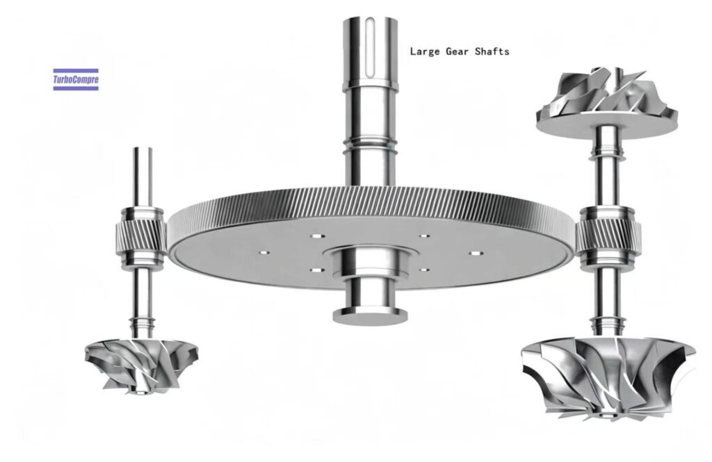
When a centrifugal compressor or turbine develops a critical component failure, reverse engineering may seem like the fastest and most economical way to manufacture a replacement. By measuring the original component and reproducing its geometry, a supplier may appear to offer a straightforward solution.
However, matching dimensions does not guarantee matching performance, strength, or service life.
For high-speed rotating machinery, even small deviations in shaft geometry, gear tooth profiles, impeller aerodynamics, material properties, or manufacturing precision can affect vibration, efficiency, bearing loads, and operational reliability. A replacement component that looks identical may still introduce hidden risks, leading to repeated failures, unexpected downtime, and costly secondary damage.
Understanding these risks is essential when selecting replacement parts for centrifugal compressors, industrial turbines, and other high-speed rotating equipment.
1. Why Reverse Measurement Alone Is Not Enough
Reverse engineering typically begins with dimensional inspection, scanning, or measurement of an existing component. These methods can help reconstruct its geometry, but they cannot independently reveal every aspect of the original design.
Critical information may include:
Material properties: Material grade, cleanliness, strength, toughness, and fatigue resistance.
Heat treatment: Hardness, case depth, residual stress, and microstructure.
Manufacturing tolerances: Geometric accuracy, surface finish, concentricity, and runout.
Operating characteristics: Rotational speed, temperature, loads, lubrication conditions, and dynamic behavior.
Design intent: Stress distribution, aerodynamic performance, gear contact patterns, and rotor dynamics.
A worn or damaged component presents an additional challenge: its current geometry may no longer represent the original design.
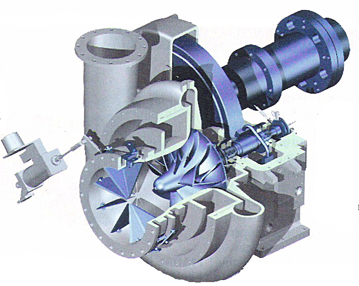
The API Standard 617 provides an important technical reference for axial and centrifugal compressors and expander-compressors used in relevant industrial services. Its scope and technical requirements demonstrate why critical rotating equipment must be evaluated beyond external dimensions alone.
2. Shaft Risks: Hidden Problems in the Heart of the Rotor
The shaft connects rotating components and transmits torque while maintaining the required alignment and mechanical stability. In a high-speed centrifugal compressor or turbine, shaft accuracy is fundamental to the entire rotor system.
otential risks of improper shaft reproduction include:
Incorrect concentricity and runout: Excessive geometric errors can increase vibration and affect bearing and seal clearances.
Inadequate material strength: Incorrect material selection or heat treatment may reduce fatigue resistance and increase the risk of cracking or failure.
Poor dimensional control: Errors in bearing journals, impeller mounting surfaces, shoulders, and fits can cause misalignment or improper assembly.
Unverified rotor dynamics: A replacement shaft may change the rotor’s mass distribution, stiffness, or critical speeds, affecting its response across the operating range.
These problems may not be obvious during static inspection. A shaft can meet basic dimensional requirements yet perform poorly under actual rotational speed, temperature, and load.
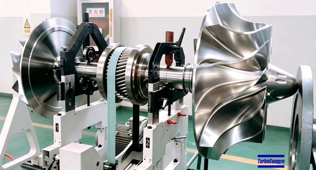
For this reason, shaft replacement should consider material verification, dimensional and geometric inspection, appropriate nondestructive testing, rotor-dynamic evaluation where required, and final assembly and balance verification.
3. Gear Risks: Small Profile Errors, Significant Consequences
In integrally geared centrifugal compressors and other geared rotating machines, the transmission system operates under high speed and load. Gear reliability depends on more than the number of teeth, pitch diameter, and external dimensions.
The critical risks include:
Incorrect tooth geometry: Errors in tooth profile, lead, helix angle, or modifications can affect load distribution and meshing accuracy.
Improper heat treatment: Insufficient hardness, incorrect case depth, or unsuitable core properties can accelerate wear, pitting, or tooth damage.
Poor contact patterns: Uneven tooth contact can concentrate loads, generate heat, and increase vibration and noise.
Inadequate lubrication compatibility: Gear geometry, surface finish, operating loads, and lubrication conditions must work together to maintain reliable operation.
High-speed gear systems are particularly sensitive to manufacturing quality because small errors can influence meshing excitation, bearing loads, and overall dynamic behavior.

Gears should therefore be evaluated through appropriate gear metrology, material and heat-treatment verification, contact-pattern inspection, and quality checks suited to the design and service conditions. For applicable special-purpose gear units, API Standard 613 is a relevant reference; other gear arrangements may require different standards.
4. Impeller Risks: Geometry Directly Affects Aerodynamic Performance
The impeller is one of the most performance-critical components in a centrifugal compressor. Its three-dimensional blade geometry determines how energy is transferred to the gas, influencing flow capacity, pressure rise, efficiency, and operating range.
Reproducing an impeller solely from external measurements can overlook important aerodynamic and mechanical details.
Common risks include:
Incorrect blade geometry: Small changes to blade angles, thickness, curvature, or splitter-blade design can affect flow behavior and compressor performance.
Excessive residual imbalance: Inadequate machining accuracy or balancing can increase vibration and bearing loads.
Insufficient structural integrity: Unsuitable material, defects, or inadequate stress evaluation can increase the risk of cracking or deformation at high speed.
Incorrect mounting and clearances: Errors in the bore, hub, mating surfaces, or assembly fit can affect rotor alignment and mechanical reliability.
A replacement impeller may fit the shaft and rotate freely while still failing to deliver the required flow, pressure, or efficiency. In severe cases, excessive vibration or mechanical stress can threaten other rotor components.

Reliable impeller manufacturing should therefore combine accurate geometry, suitable material selection, machining quality, dimensional inspection, balancing, and additional testing where required by the design and applicable specifications.
5. The System-Level Consequences: One Incorrect Part Can Affect the Entire Machine
Shafts, gears, and impellers do not operate independently. They form part of an interconnected mechanical and aerodynamic system.
For example, an incorrectly manufactured shaft may increase vibration and disturb bearing operation. A gear with poor contact may introduce additional excitation, while an impeller with incorrect geometry or residual imbalance may compromise both aerodynamic performance and rotor stability.
Potential consequences include:
Increased vibration and bearing or seal damage.
Reduced flow capacity, pressure, or energy efficiency.
Repeated maintenance and unplanned shutdowns.
Secondary damage to gears, shafts, impellers, and other components.
Higher lifecycle costs despite a lower initial replacement price.
For critical equipment, the true cost of a replacement part includes not only its purchase price but also installation, commissioning, operating efficiency, maintenance, and the financial impact of downtime.
This is why a low-cost replacement should be evaluated on its verified technical quality and total cost of ownership, rather than dimensional similarity alone.
6. A More Reliable Approach: Engineering-Based Replacement Manufacturing
Reverse engineering is not inherently unreliable. When supported by adequate engineering analysis, manufacturing controls, and verification, it can be a valuable tool for equipment repair, component localization, and extending the service life of aging machinery.
A more reliable process should include:
Establishing the design basis: Collect available original drawings, specifications, operating data, and service history.
Inspecting the existing component: Identify wear, deformation, cracks, and other damage before using measurements as manufacturing references.
Verifying materials and processes: Specify suitable materials, heat treatment, machining methods, and inspection requirements.
Controlling critical dimensions: Check geometric tolerances, surface finish, fits, and other features affecting assembly and operation.
Verifying performance and integrity: Apply appropriate balancing, nondestructive testing, dimensional inspection, and engineering calculations or simulations as required.
Checking the complete machine: Confirm assembly clearances, alignment, lubrication, protection settings, and commissioning results against applicable requirements.

Not every component requires the same testing program. Inspection and validation should be determined by the component’s function, operating conditions, failure consequences, and applicable technical specifications.
7. How Turbocompre Helps Reduce Replacement-Part Risks
At Turbocompre, we understand that replacing a critical component is not simply a matter of copying its dimensions. The objective is to restore reliable equipment operation while controlling repair costs and minimizing production downtime.
Our team specializes in centrifugal compressors, replacement components, and repair and overhaul solutions for industrial rotating equipment. With experience supporting Ingersoll Rand, Atlas Copco, Hanwha, IHI-Sullair, and other relevant compressor platforms, we work with customers to identify suitable technical solutions for aging or damaged machinery.
Our capabilities include:
Shafts and rotor components: Replacement manufacturing based on available original design information and appropriate engineering verification.
Gearboxes and gears: Technical assessment and replacement solutions for applicable centrifugal compressor configurations.
Impellers: Replacement manufacturing with attention to geometry, material selection, machining precision, and balancing requirements.
Repair and overhaul support: Component replacement, equipment refurbishment, and technical assistance aimed at restoring stable operation.
Where original drawings and verified design information are available, they can provide a stronger basis for replacement manufacturing than relying on measurements of a worn component alone. Where information is incomplete, additional inspection and engineering evaluation may be necessary before a replacement design is approved.

By combining compressor manufacturing knowledge with replacement-part and repair experience, Turbocompre aims to provide practical, cost-effective alternatives without treating critical rotating components as simple interchangeable parts.
Contact Turbocompre to discuss your equipment model, component drawings, operating conditions, and repair requirements. Our team can help assess the available information and identify a suitable replacement or overhaul solution.