
How Compressor Piping Design Affects System Performance

A compressor’s performance depends not only on its internal components but also on the piping system connected to it. Even a high-efficiency centrifugal compressor can experience reduced system performance if the piping is poorly designed.
Compressor piping design directly affects pressure loss, airflow, energy consumption, operational stability, and equipment reliability. Undersized pipes, excessive bends, poorly positioned valves, and inadequate drainage can create unnecessary resistance and increase operating costs.
For industrial plants operating continuously, these issues can lead to significant energy waste and production disruptions. Proper piping design should therefore be considered an essential part of compressor system engineering, not simply an installation task.
1. Pressure Drop and Energy Efficiency
Pressure drop is one of the most important factors in compressed air piping design. As compressed air flows through pipes, elbows, valves, filters, and other components, friction and flow resistance reduce the available pressure.
When pressure at the point of use falls below the required level, operators may increase the compressor discharge pressure to compensate. However, this approach forces the compressor to work harder and can increase electricity consumption.
According to the U.S. Department of Energy, excessive pressure drop can significantly affect system performance and energy use. Its industrial compressed air guidance recommends minimizing pressure losses throughout the supply and distribution system.
To reduce unnecessary pressure drop:
Select pipe diameters based on maximum expected flow, operating pressure, pipe length, and allowable pressure loss.
Minimize unnecessary elbows, restrictions, and abrupt changes in pipe diameter.
Select valves, filters, aftercoolers, and dryers with suitable flow capacity and acceptable pressure-drop characteristics.
Measure pressure at multiple points to identify where excessive losses occur.
For more guidance, see the U.S. Department of Energy’s Improving Compressed Air System Performance Sourcebook.
2. Correct Pipe Sizing for Stable Airflow
Pipe diameter has a direct influence on airflow velocity and pressure loss. An undersized pipe increases velocity and friction, potentially restricting the compressor’s ability to deliver the required flow at the specified pressure.
Oversized piping, on the other hand, increases installation costs and may create unnecessary space and support requirements. The objective is to select an economical pipe size that meets the system’s operating requirements without compromising performance.
Engineers should consider the following factors:
Maximum and minimum operating flow rates.
Operating and design pressures.
Pipe length and the number of fittings.
Gas properties, temperature, and compressibility.
Allowable pressure drop and future capacity requirements.
For centrifugal compressors, flow conditions are particularly important because the compressor’s operating point depends on the interaction between its performance curve and the system resistance. Excessive downstream resistance can affect delivered flow and may contribute to unstable operation in certain circumstances.
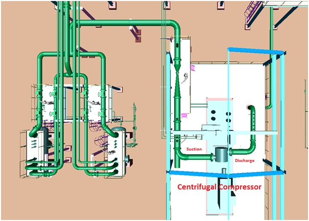
Pipe sizing should therefore be verified through engineering calculations rather than selected solely from the compressor’s connection diameter.
3. Pipe Layout, Elbows, and Valves
The physical arrangement of piping influences flow resistance, accessibility, maintenance, and overall system reliability.
Sharp bends, unnecessary tees, sudden expansions, and poorly selected valves can create additional turbulence and pressure losses. These effects become increasingly important in large-flow industrial centrifugal compressor systems.
A well-designed layout should:
Use long-radius elbows where practical to reduce flow resistance.
Minimize unnecessary changes in direction and diameter.
Avoid placing restrictive fittings immediately at critical compressor connections unless permitted by the manufacturer.
Provide sufficient space for valve operation, inspection, and maintenance.
Arrange isolation and check valves according to the system design and compressor manufacturer’s requirements.
The discharge piping of a centrifugal compressor requires particular attention. The connection should not impose excessive mechanical loads on the compressor casing or create unnecessary backpressure.

Piping arrangements should also be reviewed for interactions with other equipment, including aftercoolers, air receivers, filters, and downstream process machinery.
4. Vibration, Thermal Expansion, and Mechanical Stress
Piping design affects not only airflow but also the mechanical loads transmitted to the compressor.
Poorly supported pipes, excessive deadweight, thermal expansion, and vibration can place unwanted forces and moments on compressor nozzles and connected equipment. Over time, these conditions may contribute to leakage, fatigue, damaged supports, or other mechanical problems.
To minimize these risks, engineers should:
Design pipe supports and restraints for the actual operating loads.
Account for thermal expansion and contraction.
Assess vibration and pressure pulsation where relevant.
Use suitable flexible connectors or expansion joints only where appropriate and permitted by the engineering design.
Verify allowable nozzle loads against the compressor manufacturer’s requirements.
Flexible connectors should not be used as a substitute for proper pipe support or alignment. For large centrifugal compressors, a piping stress analysis may be necessary to confirm that loads remain within acceptable limits.
Mechanical integrity is particularly important in continuous-process industries, where unexpected compressor shutdowns can interrupt production and increase maintenance costs.
5. Condensate Drainage and Air Quality
Compressed air may contain moisture that condenses as the gas cools. If piping does not provide appropriate drainage, condensate can accumulate and cause corrosion, pressure losses, contamination, or damage to downstream equipment.
A reliable piping arrangement should consider:
Pipe slopes and low-point drainage where appropriate.
Moisture separators and automatic drains.
Aftercooler and dryer locations.
Drainage access for inspection and maintenance.
Protection against condensate flowing back toward the compressor.
For general compressed air distribution systems, appropriate drainage and moisture management help preserve air quality and reduce corrosion-related problems.

Process gas applications require additional care. Depending on the gas composition, operating pressure, and temperature, engineers may need to consider material compatibility, liquid formation, contamination risks, and specialized separation requirements.
Piping materials and drainage arrangements must be selected according to the actual gas service rather than applying general compressed air practices to every application.
6. Inlet and Discharge Piping for Centrifugal Compressors
Centrifugal compressors require careful coordination between inlet conditions, discharge piping, and the overall process system.
Inlet piping: Excessive inlet resistance reduces the pressure available at the compressor inlet and can affect capacity and power consumption. The inlet arrangement should minimize unnecessary restrictions and avoid flow disturbances that could interfere with the compressor’s performance.
Discharge piping: Excessive resistance increases the pressure the compressor must overcome to deliver gas into the downstream system. Incorrectly arranged check valves, control valves, and other restrictions can also affect operating conditions.

For both inlet and discharge piping, engineers should verify pipe dimensions, gas velocity, pressure loss, connection loads, and the manufacturer’s installation requirements.
Centrifugal compressors must also operate within their specified performance envelope. Depending on the compressor design and operating conditions, changes in system resistance can influence surge margin and operating stability. Anti-surge protection, where required, should be engineered as part of the complete compressor and process control system.
7. How Turbocompre Supports Reliable Compressor System Performance
At Turbocompre, we understand that reliable compressed air production depends on more than the compressor itself. Equipment selection, piping layout, operating conditions, and maintenance planning all contribute to overall system performance.
Turbocompre specializes in industrial centrifugal compressors and related services, supporting applications that require reliable airflow, stable pressure, and cost-effective operation.
Our engineering and manufacturing capabilities help customers evaluate compressor requirements and select suitable equipment for their applications. When planning a new compressor installation or upgrading an existing system, the relationship between compressor performance and piping resistance should be considered from the beginning.
For customers seeking high-quality centrifugal compressor solutions, Turbocompre focuses on dependable performance, responsive technical support, and competitive cost of ownership.

Contact Turbocompre today to discuss your compressor requirements and develop a reliable, energy-conscious solution for your plant.